Calibrator pipeline
Note
These instructions are outdated and only valid for prefactor 3.2 or older. Please check the recent instructions page.
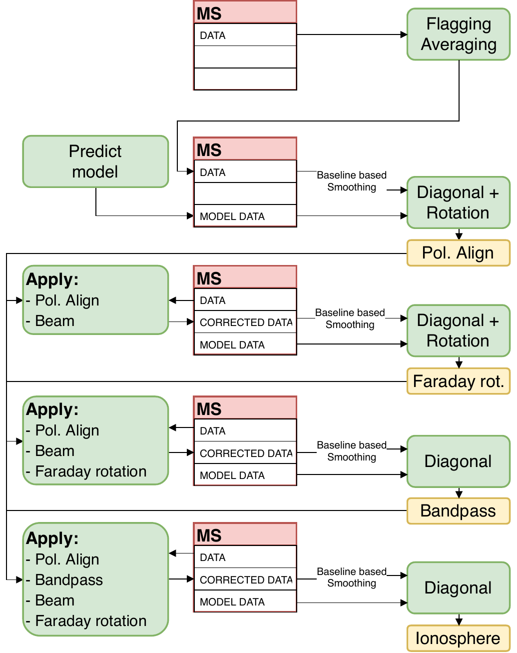
This pipeline processes the calibrator data in order to derive direction-independent corrections.
It will take into account the correct order of distortions to be calibrated for.
This chapter will present the specific steps of the calibrator pipeline in more detail.
You will find the single steps in the parameter pipeline.steps in line 98.
All results (diagnostic plots and calibration solutions) are usually stored in a subfolder of the results directory, see inspection_directory (line 79) and cal_values_directory (line 80), respectively.
Prepare calibrator (incl. “demixing”)
This part of the pipeline prepares the calibrator data in order to be calibration-ready. This mainly includes mitigation of bad data (RFI, bad antennas, contaminations from A-Team sources), selection of the data to be calibrated (usually Dutch stations only), and some averaging to reduce data size and enhance the signal-to-noise ratio. The user can specify whether to do raw data or pre-processed data flagging and whether demixing should be performed.
The basic steps are:
mapping of data to be used (
createmap_cal)creating a model of A-Team sources to be subtracted (
make_sourcedb_ateam)- basic flagging and averaging (
ndppp_prep_cal) edges of the band (
flagedge) – only used inraw_flaggingmodestatistical flagging (
aoflag) – only used inraw_flaggingmodebaseline flagging (
flag)low elevation flagging (below 20 degress elevation) (
elev)demix A-Team sources (
demix) – only used if specifiedinterpolation of flagged data (
interp)averaging of the data to 4 sec and 4 channels per subband (
avg)
- basic flagging and averaging (
wide-band statistical flagging (
aoflag)find needed skymodel of calibrator automatically (
sky_cal)write the calibrator skymodel into the MODEL_DATA column (
predict_cal)interpolate flagged data from the wide-band statistical flagging step (
interp_cal)baseline-dependent smoothing of the data (
smooth_data)perform direction-independent phase-only calibration (diagonal terms + common rotation angle) (
calib_cal)
The solutions are stored in the h5parm file format.
Calibration of the polarization alignment (PA)
The phase solutions derived from the preparation step are now collected and loaded into LoSoTo. LoSoTo will derive the polarizion alignment and provide diagnostic plots:
polalign_ph_pol??: matrix plot of the phase solutions for the XX and YY polarization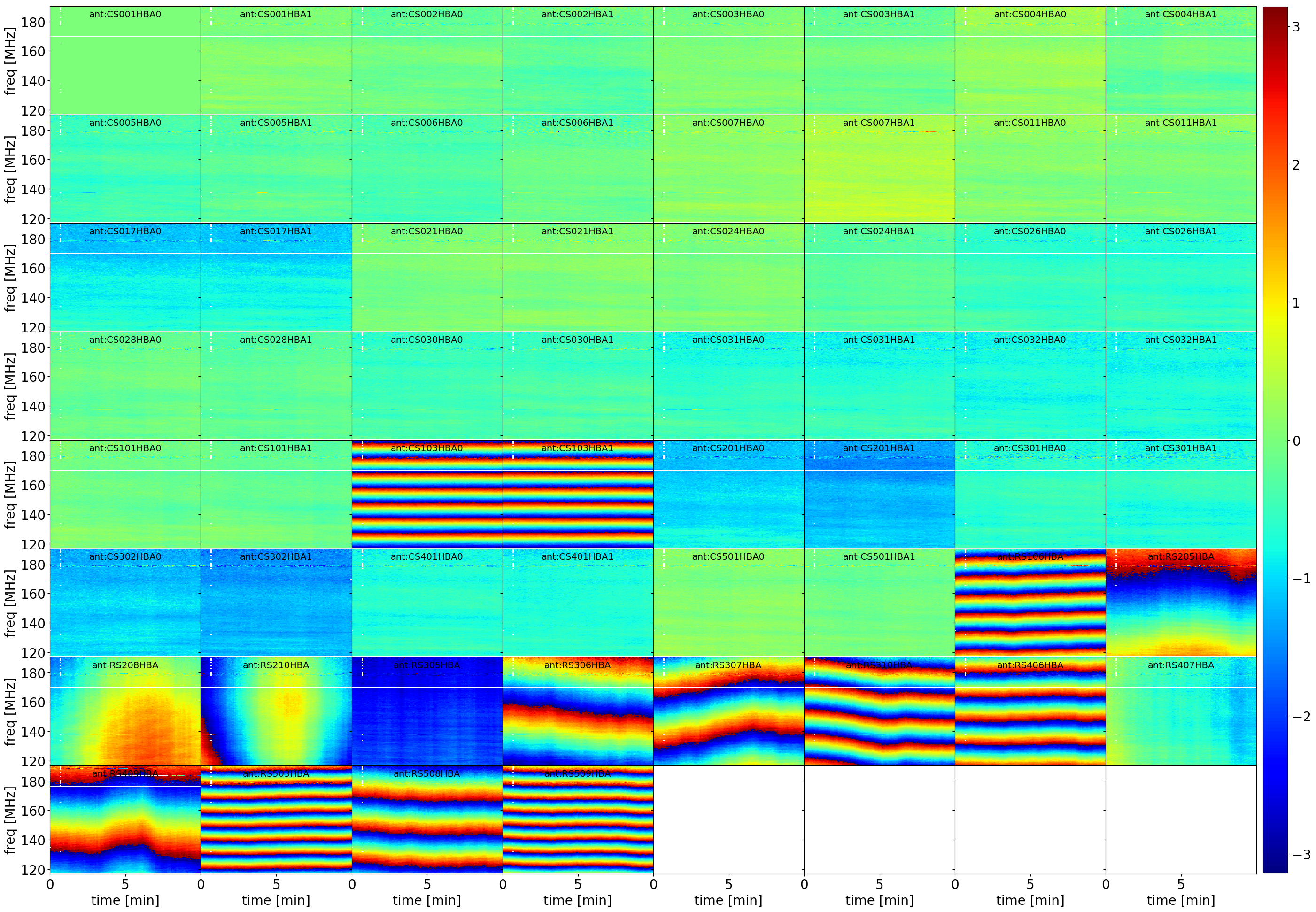
polalign_ph_poldif: matrix plot of the phase solutions from XX-YY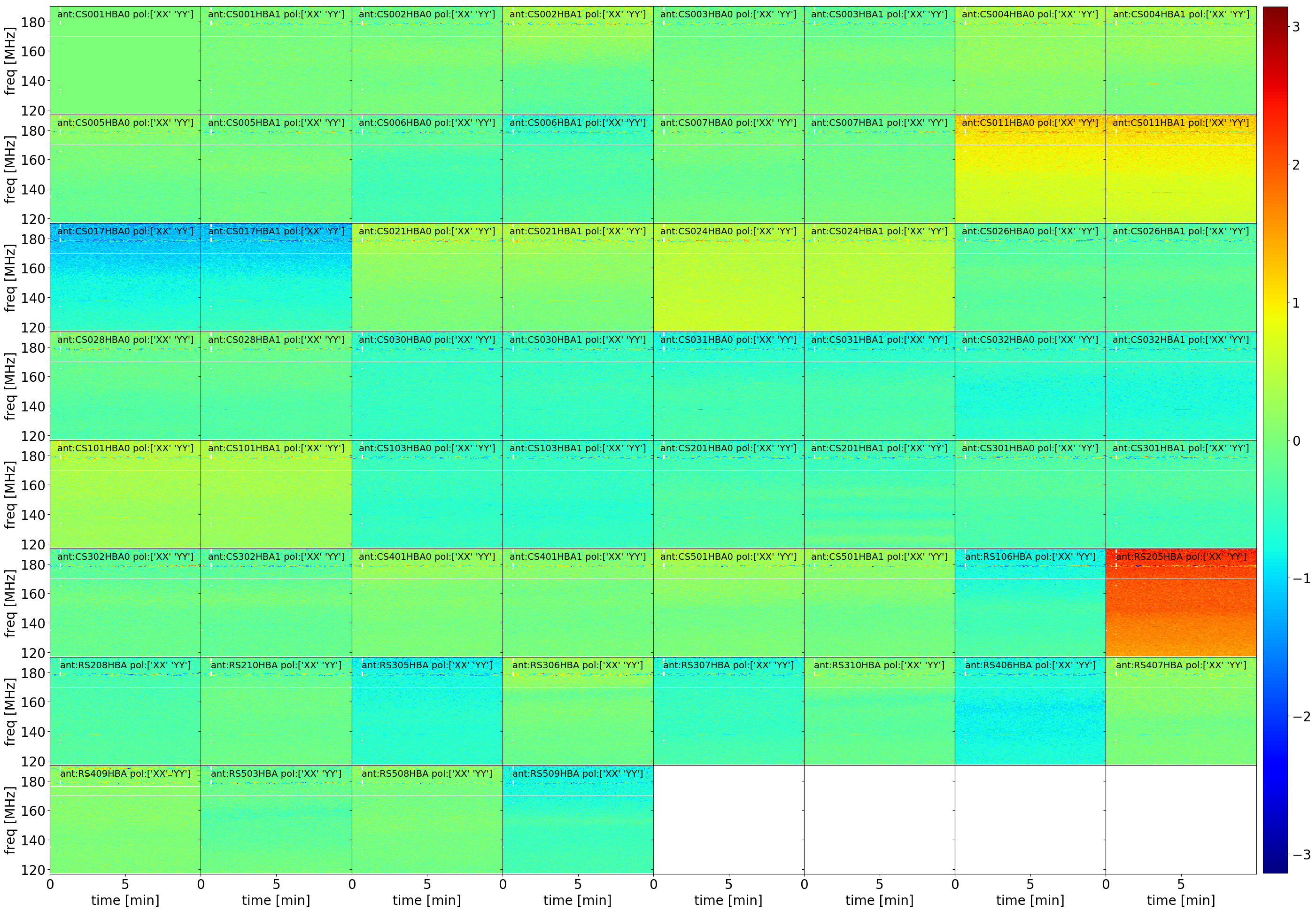
polalign_rotange: matrix plot of the common rotation angle solutions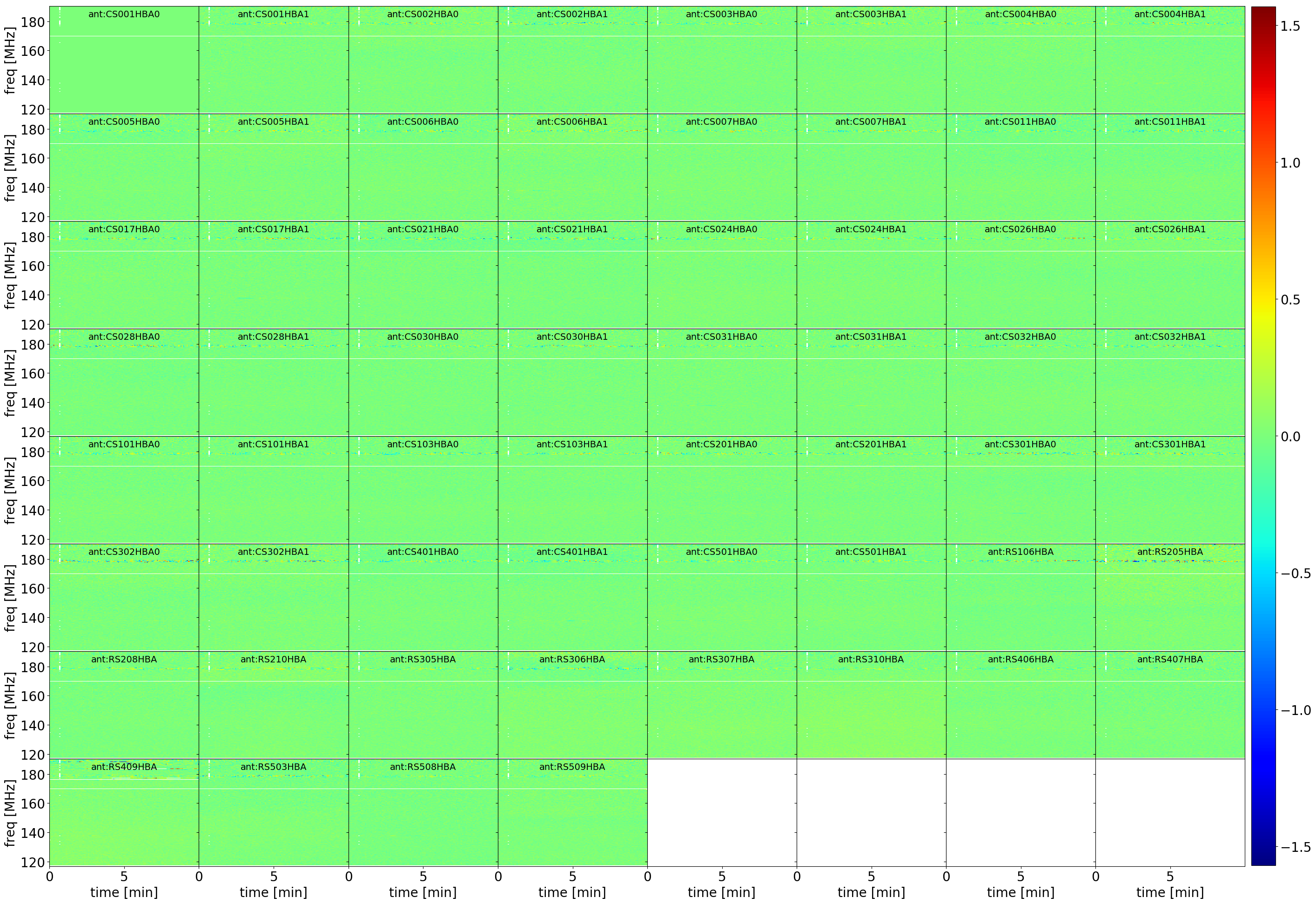
polalign_amp_pol??: matrix plot of the amplitude solutions for the XX and YY polarization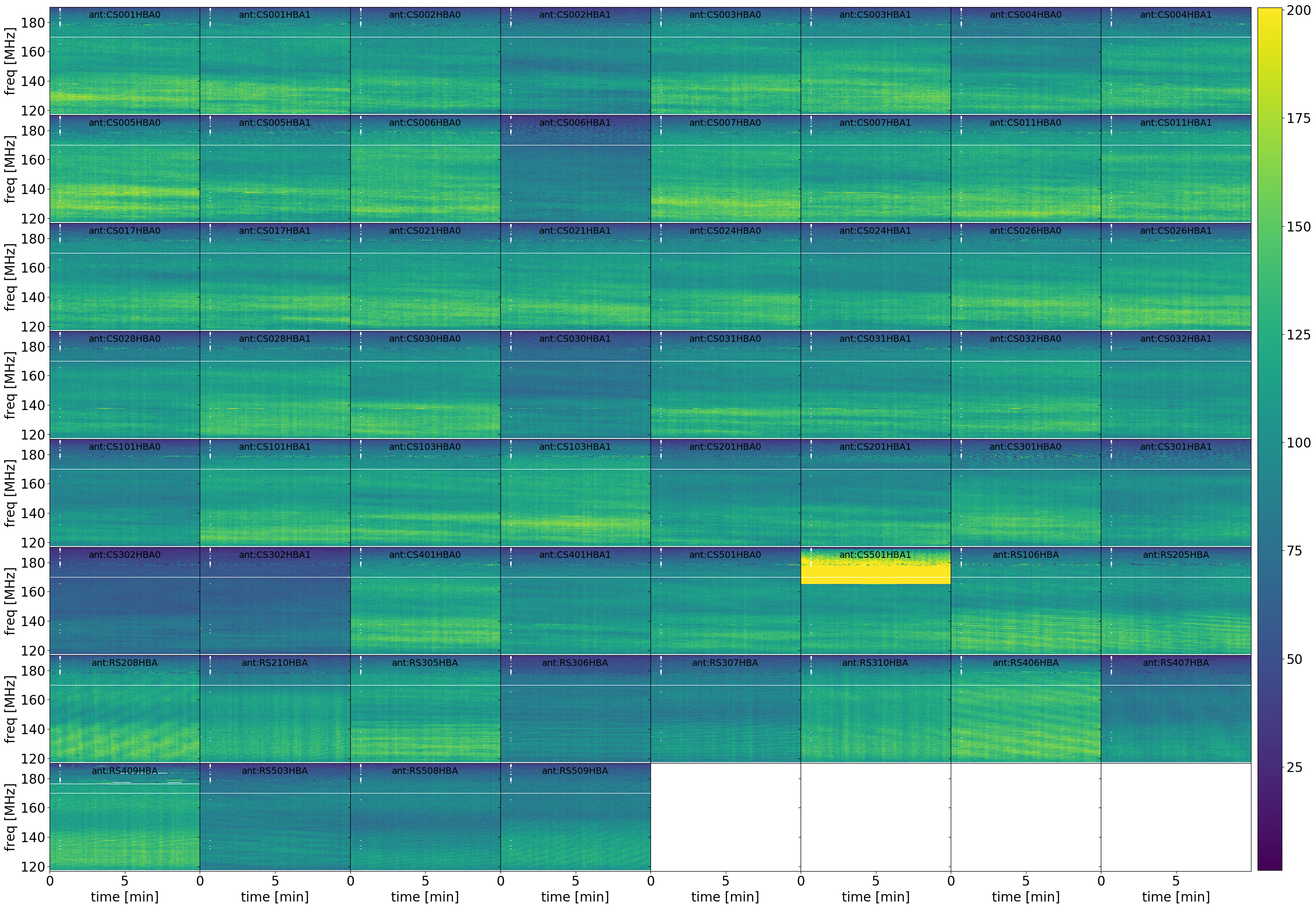
polalign: matrix plot of the derived polarization alignment between XX and YY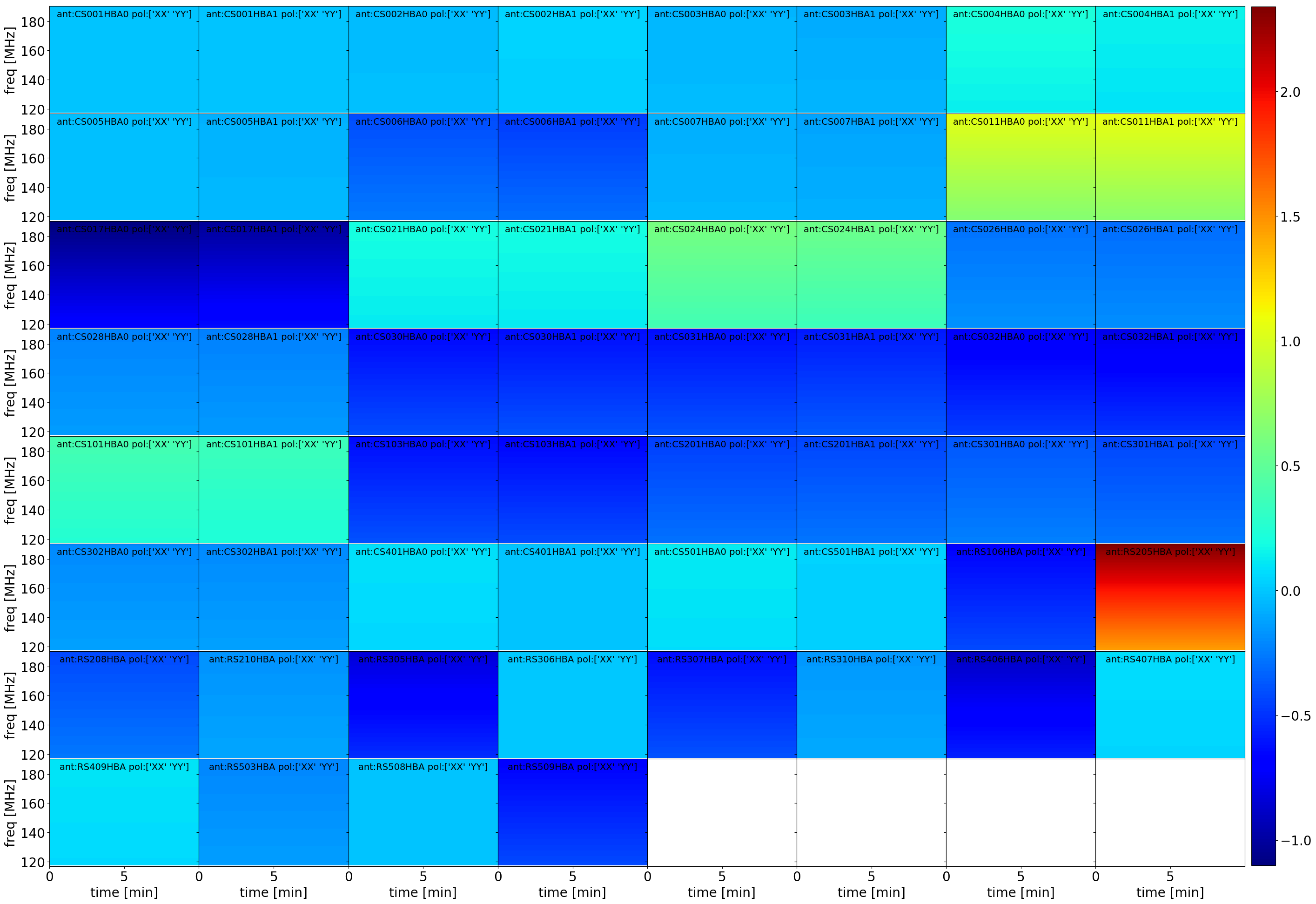
polalign_ph-res_pol??: matrix plot of the residual phase solutions for the XX and YY polarization after subtraction the derived polarization alignmentpolalign_ph-res_poldif: matrix plot of the residual phase solutions for XX-YY after subtraction of the derived polarization alignment
The solutions are then stored in the final calibrator solution set cal_solutions (line 83) and applied to the interpolated data (apply_PA), together with the LOFAR beam correction (apply_beam)
The calibration (calib_cal) is then repeated on the corrected and re-smoothed data (smooth_corrected).
Calibration of the Faraday Rotation (FR)
The outcome of the re-calibration after correcting for the polarization alignment is again loaded into LoSoTo in order to derive corrections for Faraday Rotation. The following diagnostic plots are created:
fr_ph_pol??: matrix plot of the phase solutions for the XX and YY polarizationfr_ph_poldif: matrix plot of the phase solutions from XX-YYfr_rotange: matrix plot of the common rotation angle solutionsfr_amp_pol??: matrix plot of the amplitude solutions for the XX and YY polarizationfr: matrix plot of the derived differential Rotation Measure from Faraday Rotation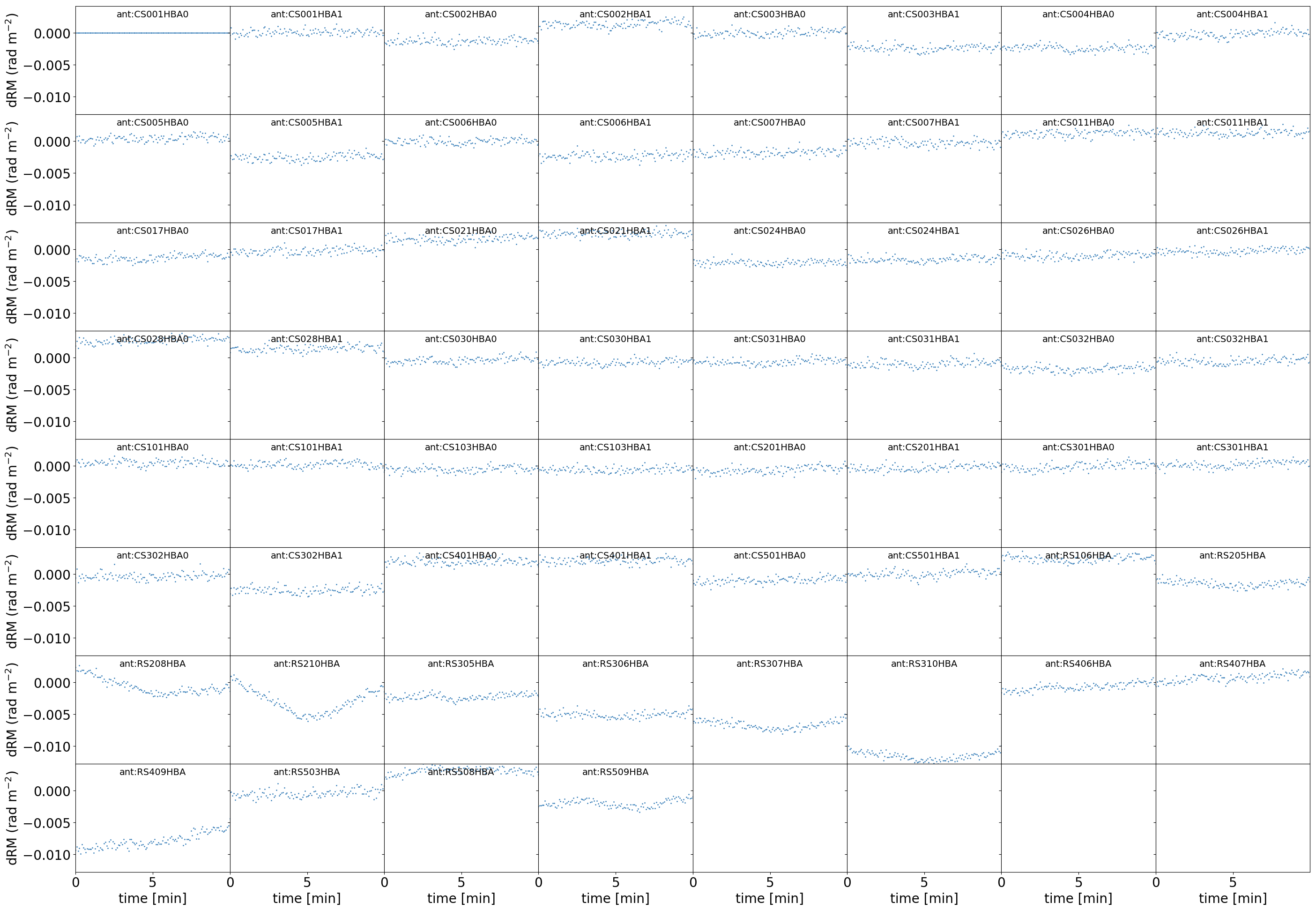
fr_ph-res_pol??: matrix plot of the residual phase solutions for the XX and YY polarization after subtraction the derived Rotation Measurefr_ph-res_poldif: matrix plot of the residual phase solutions for XX-YY after subtraction of the derived Rotation Measure
The solutions are then stored in the final calibrator solution set cal_solutions (line 83) and applied, together with the polarization alignment and the LOFAR beam correction, to the interpolated data (apply_PA + apply_beam + apply_FR).
The calibration (calib_cal) is then repeated on the corrected and re-smoothed data (smooth_corrected).
Calibration of the Bandpass (bandpass)
The outcome of the re-calibration after correcting for the polarization alignment and Faraday Rotation is loaded into LoSoTo in order to derive corrections for the bandpass. A robust flagging on the amplitude solutions as well as a Savitzky-Golay filter is applied in order to reject bad solutions and smooth the outcome. Frequency regimes up to a certain maximum width (maxFlaggedWidth) will be interpolated if flagged.
The following diagnostic plots are created:
ampBFlag__??: matrix plot of the amplitude solutions for the XX and YY polarizationbeforeflagging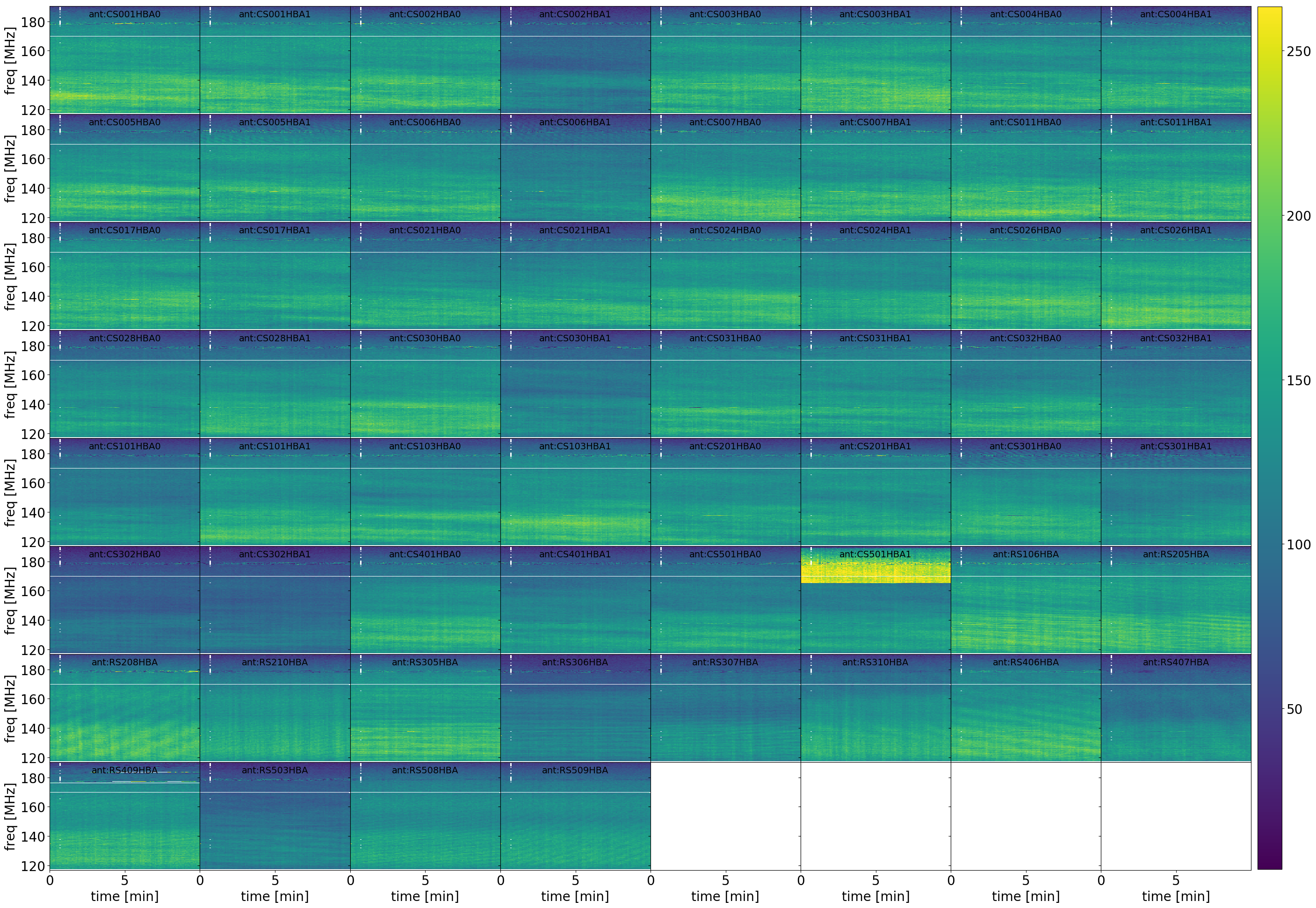
ampAFlag__??: matrix plot of the amplitude solutions for the XX and YY polarizationafterflagging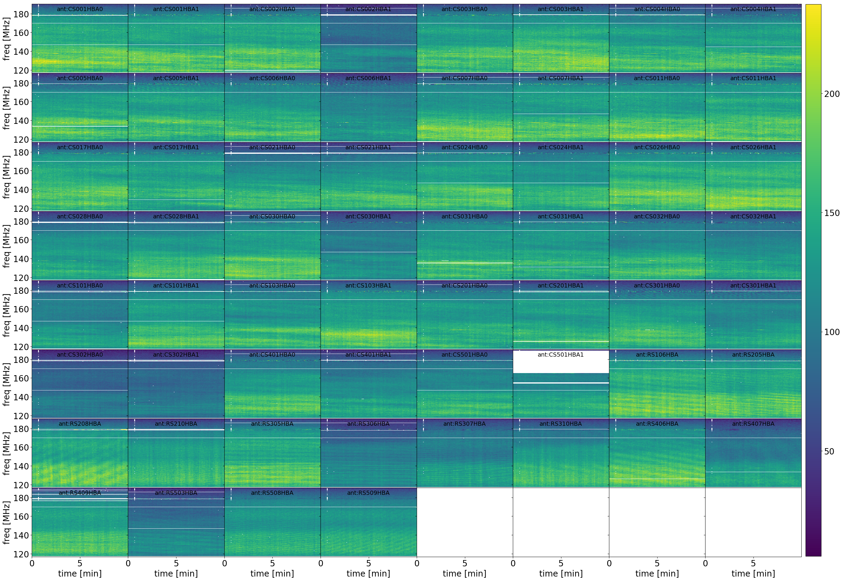
bandpass_pol??: the derived bandpass of all stations in the XX and YY polarizationbandpass_time??: matrix plot of the derived bandpass, where both polarizations are colorcoded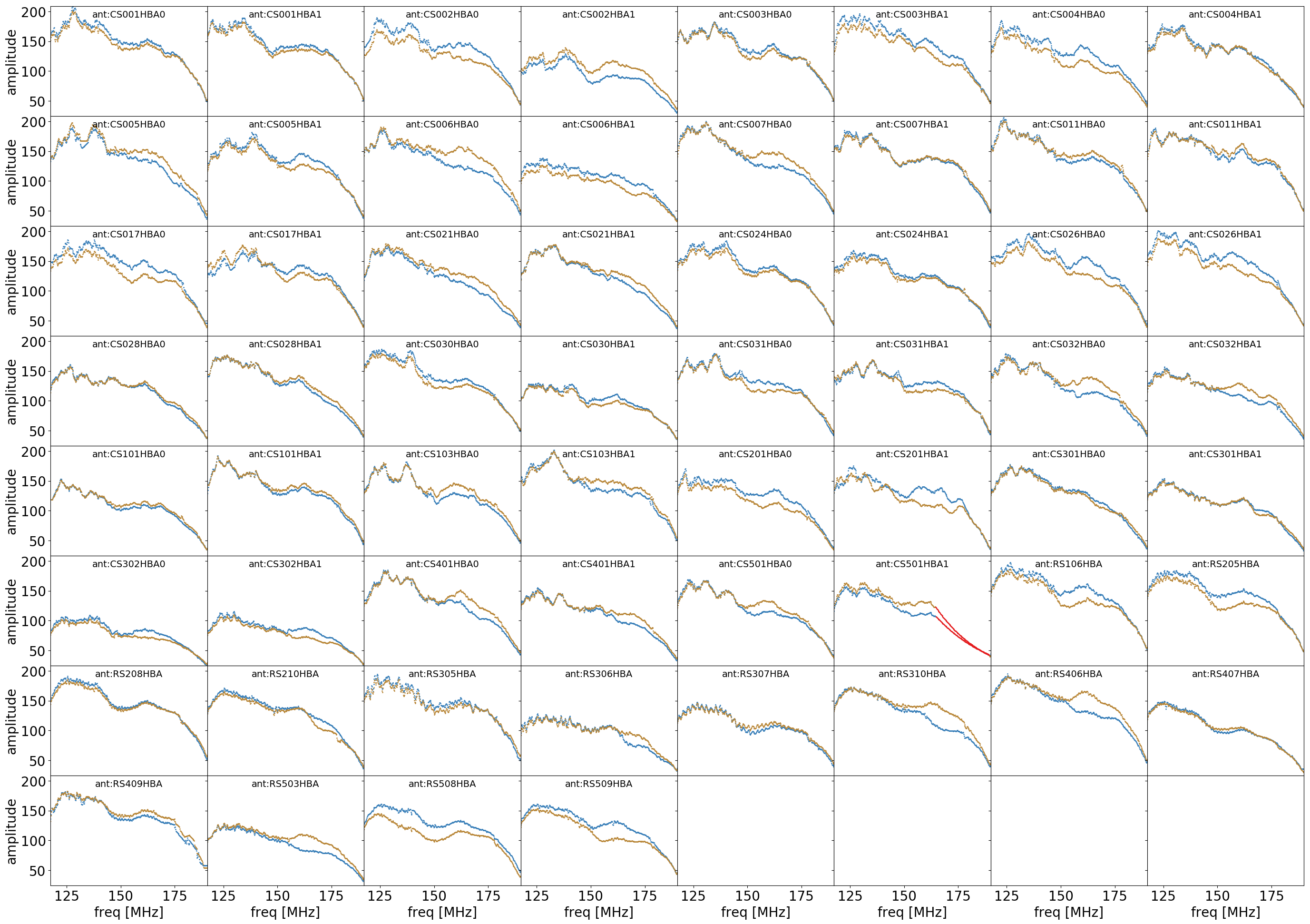
bandpass_time??_pol??: plot of the derived bandpass of the XX and YY polarization, where all stations are colorcoded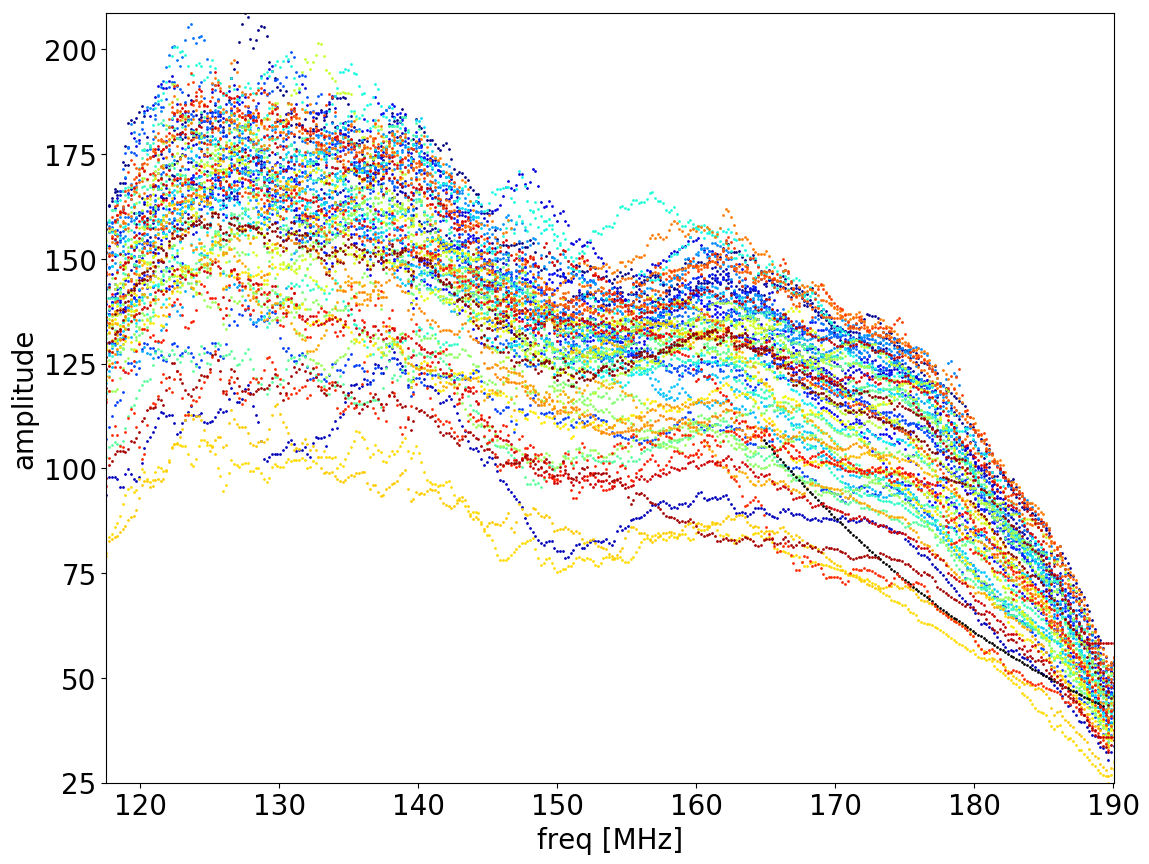
The solutions are then stored in the final calibrator solution set cal_solutions (line 83) and applied, together with the polarization alignment, the LOFAR beam correction and the Faraday Rotation corrections to the interpolated data in the correct order (apply_PA + apply_bandpass + apply_beam + apply_FR ).
The calibration (calib_cal) is then repeated on the corrected and re-smoothed data (smooth_corrected).
Calibration of the instrumental and ionospheric delays (ion)
The outcome of the re-calibration after correcting for the polarization alignment, the bandpass and the Faraday Rotation is loaded into LoSoTo in order to derive corrections for the instrumental and ionospheric delays. A robust flagging on the amplitude solutions is applied in order to reject bad solutions. These flags are applied to the phase solutions. These phase solutions should be mainly affected by instrumental (clock) and ionospheric (TEC) delays. This LoSoTo step will aim for seperating both effects (clock-TEC separation). The following diagnostic plots are created:
ion_ampBFlag__??: matrix plot of the amplitude solutions for the XX and YY polarization before flaggingion_ampAFlag__??: matrix plot of the amplitude solutions for the XX and YY polarization after flaggingion_ph_pol??: matrix plot of the phase solutions for the XX and YY polarizationion_ph_poldif: matrix plot of the phase solutions from XX-YYclock: matrix plot of the derived (instrumental) clock offsets in seconds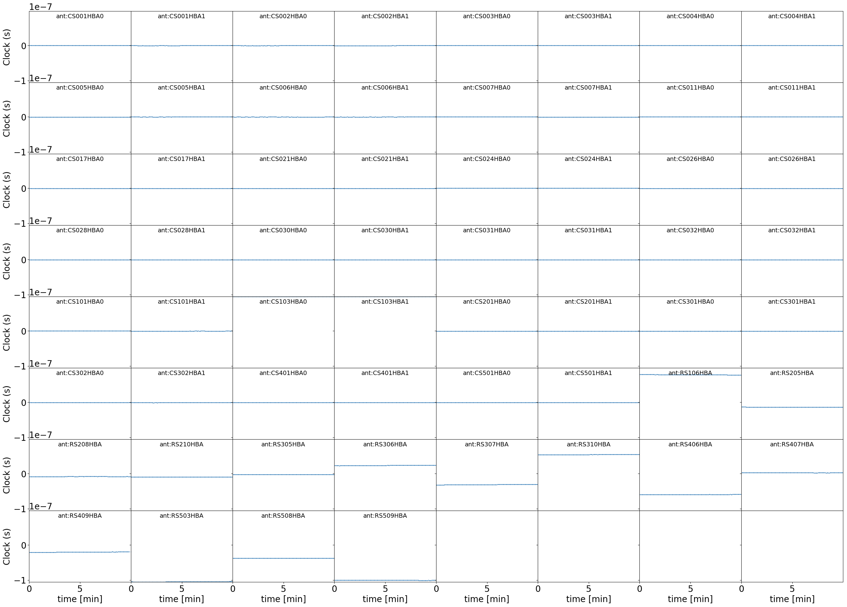
tec: matrix plot of the derived differential TEC in TECU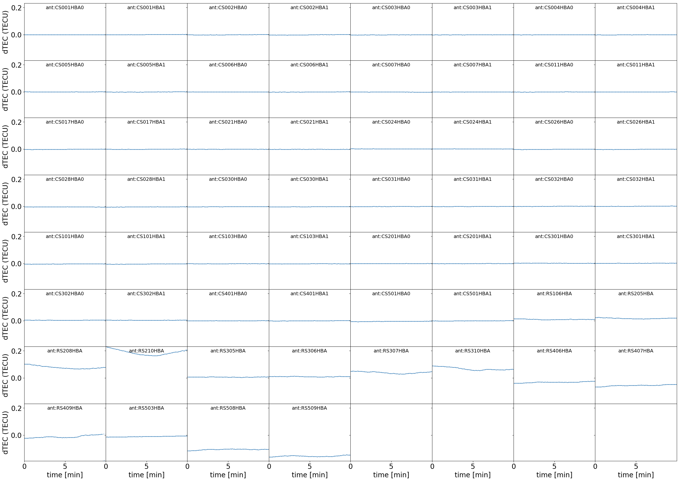
ion_ph-res_pol??: matrix plot of the residual phase solutions for the XX and YY polarization after subtraction the derived instrumental and ionospheric delaysion_ph-res_poldif: matrix plot of the residual phase solutions for XX-YY after subtraction of the derived instrumental and ionospheric delays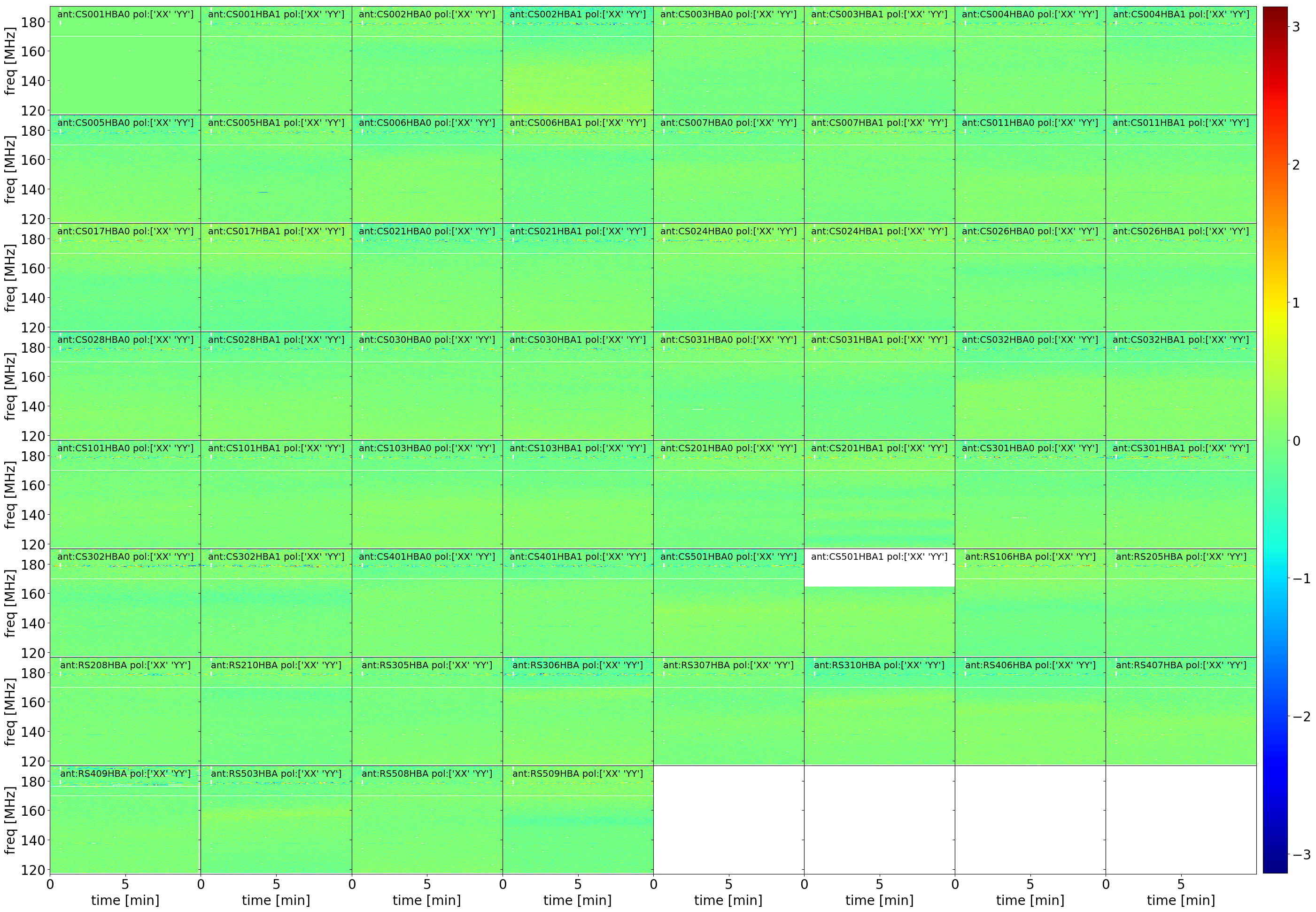
The solutions are then stored in the final calibrator solution set cal_solutions (line 83).
User-defined parameter configuration
Parameters you will need to adjust
Information about the input data
cal_input_path: specify the directory where your calibrator data is stored (a full UNIX-compatible directory is required)cal_input_pattern: regular expression pattern of all your calibrator files (e.g.L72318*.MS)
Location of the software
prefactor_directory: full path to your prefactor copylosoto_directory: full path to your local LoSoTo installationaoflagger: full path to your aoflagger executable
Parameters you may need to adjust
Data selection and calibration options
refant:name of the station that will be used as a reference for the phase-plotsflag_baselines: NDPPP-compatible pattern for baselines or stations to be flagged (may be an empty list, i.e.:[])process_baselines_cal: performs A-Team-clipping/demixing and direction-independent phase-only self-calibration only on these baselines. Choose [CR]S*& if you want to process only cross-correlations and remove international stations.filter_baselines: selects only this set of baselines to be processed. Choose [CR]S*& if you want to process only cross-correlations and remove international stations.do_smooth: enable or disable baseline-based smoothingrfistrategy: strategy to be applied with the statistical flagger (AOFlagger), default:HBAdefault.rfismax_length: amount of subbands to concatenate for full-bandwidth flagging (for an HBA calibrator, you can take all SBs if memory allows)max2interpolate: amount of channels in which interpolation should be performed for deriving the bandpass (default: 30)interp_windowsize: size of the window over which a value is interpolated. Should be odd. (default: 15)ampRange: range of median amplitudes accepted per stationskip_international: skip fitting the bandpass for international stations (this avoids flagging them in many cases)raw_data: use autoweight, set to True in case you are using raw data (default: False)propagatesolutions: use already derived solutions as initial guess for the upcoming time slotmaxStddev: maximum allowable standard deviation when outlier clipping is done. For phases, this should value should be in radians, for amplitudes in log(amp). If None (or negative), a value of 0.1 rad is used for phases and 0.01 for amplitudes
A comprehensive explanation of the baseline selection syntax can be found here.
Demixing options (only used if demix step is added to the prep_cal_strategy variable)
demix_sources: choose sources to demix (provided as list), e.g.,[CasA,CygA]demix_target: if given, the target source model (its patch in the SourceDB) is taken into account when solving (default:"")demix_freqstep: number of channels to average when demixing (default: 16)demix_timestep: number of time slots to average when demixing (default: 10)
Definitions for pipeline options
default_flagging: regular flagging steps after pre-processing by the observatory pipelines (default:flag,elev,flagamp)raw_flagging: full set flagging steps (usually only necessary for raw data, default:flagedge,aoflag,{{ default_flagging }})1st_order: steps for first order clock-TEC separation (Do not change! Onlycal_ionshould be edited if needed, default:ct,plotTEC,residuals)3rd_order: steps for third order clock-TEC separation (Do not change! Onlycal_ionshould be edited if needed, default:ct3,plotTEC3,residuals3)prep_cal_strategy: steps to be performed for the preparation of the calibrator data. Add,demixif you want to enable demixing. (default:{{ default_flagging }})cal_ion: choose whether you want to perform 1st or 3rd order ionospheric effects during clock-TEC separation (default:{{ 1st_order }})
Parameters for pipeline performance
num_proc_per_node: number of processes to use per step per node (default:input.output.max_per_node, reads the parametermax_per_nodefrom thepipeline.cfg)num_proc_per_node_limit: number of processes to use per step per node for tasks with high I/O (DPPP or cp) or memory (e.g. calibration) (default: 4)max_dppp_threads: number of threads per process for NDPPP (default: 10)memoryperc: maximum of memory used for aoflagger in raw_flagging mode in percentmin_length: minimum amount of subbands to concatenate in frequency necessary to perform the wide-band flagging in the RAM. It data is too big aoflag will use indirect-read.overhead: Only use this fraction of the available memory for deriving the amount of data to be concatenated.min_separation: minimal accepted distance to an A-team source on the sky in degrees (will raise a WARNING)error_tolerance: defines whether pipeline run will continue if single bands fail (default: False)
Parameters you may want to adjust
Main directories
lofar_directory: base directory of your LOFAR installation (default: $LOFARROOT)job_directory: directory of the prefactor outputs (usually thejob_directoryas defined in thepipeline.cfg, default:input.output.job_directory)
Script and plugin directories
scripts: location of the prefactor scripts (default:{{ prefactor_directory }}/scripts)pipeline.pluginpath: location of the prefactor plugins: (default:{{ prefactor_directory }}/plugins)
Skymodel directory
calibrator_path_skymodel: location of the prefactor skymodels (default:{{ prefactor_directory }}/skymodels)
Result directories
results_directory: location of the prefactor results (default:{{ job_directory }}/results)inspection_directory: location of the inspection plots (default:{{ results_directory }}/inspection)cal_values_directory: directory of the calibration solutions (h5parm file, default:{{ results_directory }}/cal_values)
Location of calibrator solutions
cal_solutions: location of the calibration solutions (h5parm file, default:{{ cal_values_directory }}/cal_solutions.h5)
Averaging for the calibrator data
avg_timeresolution: final time resolution of the data in seconds after averaging (default: 4)avg_freqresolution: final frequency resolution of the data after averaging (default: 48.82kHz, which translates to 4 channels per subband)bandpass_freqresolution: frequency resolution of the bandpass solution table (default: 195.3125kHz, which translates to 1 channel per subband)
Parameters for HBA and LBA observations
parameter |
HBA |
LBA |
|
False |
True |
|
HBAdefault.rifs |
LBAdefaultwideband.rfis |
|
{{ 1st_order }} |
{{ 3rd_order }} |
|
clock |
phaseOrig |
In case of LBA observation you might also want to enable demixing in the prep_cal_strategy variable.
